Highlight:
intelligent fire alarm control panel
, fire alarm panel with gas extinguishing
, fire safety equipment with warranty
Product Overview
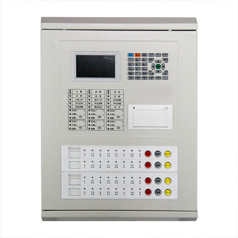
This JB-QB-QTC5015 fire alarm control panel (integrated) is an intelligent fire alarm and linkage control system that integrates fire alarm and gas extinguishing control functions into one unit. With wall-mounted structure and modular design, it features a large color Chinese character LCD display and built-in printer. It can connect with smoke detectors, heat detectors, manual call points, sounder strobes, gas discharge indicators, and input/output modules. The control panel supports gas extinguishing control for 4 independent fire zones and fire alarm functions for 1 loop, with up to 255 addressable points on the alarm loop. It complies with GB 4717-2005 and GB 16806-2006 standards, suitable for fire alarm and linkage control in shopping malls, hotels, office buildings, data centers, hospitals, schools, and industrial facilities.

Applicable Places
This control panel is widely used in the following commercial, public, and industrial buildings:
-
Commercial Complexes: Shopping malls, department stores, supermarkets, brand stores
-
Hotels & Restaurants: Star-rated hotels, business hotels, restaurants, banquet halls, conference centers
-
Office Buildings: Office towers, business centers, industrial park offices, government buildings
-
Educational & Healthcare: Hospitals, schools, libraries, museums, cinemas, exhibition halls
-
Data Centers: Server rooms, communication hubs, bank data centers, cloud computing centers
-
Industrial Facilities: Factory workshops, warehouses, electrical rooms, control rooms, production plants
-
Transportation Hubs: Airport terminals, railway stations, subway stations, passenger transport centers
-
Special Places: Archives, valuable goods storage, precision instrument rooms, heritage sites
Core Advantages
1. Integrated Alarm and Linkage Powerful Functionality
This control panel integrates fire alarm and gas extinguishing control in one unit, eliminating the need for additional gas extinguishing controllers, significantly reducing system cost and installation space. It supports gas extinguishing control for 4 independent fire zones, enabling delay start, emergency start/stop, sounder strobe activation, and discharge feedback functions. It also features 1 fire alarm loop with up to 255 addressable points, meeting the fire protection requirements of medium to large buildings.
2. Modular Design Flexible Configuration
Adopting modular plug-in structure, the panel consists of main control section, loop section, dedicated line section, gas extinguishing control section, and power supply. Modules can be flexibly configured according to project requirements. Later expansion or maintenance only requires plugging or unplugging corresponding modules without replacing the whole unit, significantly reducing upgrade costs. It can be configured with up to 6 three-wire dedicated control points with open circuit and short circuit detection, ensuring reliable control of important equipment such as fire pumps and smoke exhaust fans.
3. Color Chinese Display Intuitive Operation
Equipped with a 4-inch color Chinese character LCD display with 480×272 resolution, providing clear and intuitive display. The full Chinese menu interface allows easy operation through simple button presses without memorizing complex commands. The built-in micro printer can print all alarm, fault, and operation information in Chinese, facilitating duty records and event tracing.
4. Non-Polarized Two-Bus Easy Installation
Using non-polarized two-bus technology for field device connection, emergency start/stop buttons, gas discharge indicators, sounder strobes, and manual/auto switch modules can be easily connected. Wiring does not require polarity distinction, significantly reducing installation difficulty and labor costs. The communication distance can reach up to 1000 meters, supporting large building coverage and reducing the need for relay equipment.
5. Multiple Protection Safe and Reliable
The loop adopts isolation design with strong anti-interference performance, ensuring system stability and reliability. It features automatic main/standby power switching. Main power is AC220V, and standby power uses 12V/12AH sealed lead-acid batteries. When main power fails, it automatically switches to standby power, ensuring continuous system operation. Comprehensive fault detection includes main power fault, standby power fault, bus fault, and device fault, promptly identifying and indicating abnormalities.
6. Networking Function Centralized Monitoring
Through CAN bus, it can network with JB-TG-TC5000, JB-LT-TC5200 and other fire alarm control panels to form a fire alarm and gas extinguishing control system. RS485 interface can connect to graphic display devices in the fire control room for remote centralized monitoring. It supports slave mode operation, facilitating the construction of hierarchical fire alarm networks in large building complexes.
7. On-Site Programming Customizable
With comprehensive on-site programming capability, linkage logic programming and Chinese annotation input can be performed through the control panel keyboard or USB connection to a computer. It supports both standard linkage programming and offline programming methods. Linkage formulas support wildcards, AND/OR logic, counting conditions, and other complex logical relationships, meeting personalized linkage requirements of various buildings.
Technical Specifications
Terminal Block Description
Gas Extinguishing Zone Address Allocation
| Device Type |
Zone 1 |
Zone 2 |
Zone 3 |
Zone 4 |
| I/O Module (Discharge Start Output) |
1 |
51 |
101 |
151 |
| Input Module (Discharge Feedback) |
2-10 |
52-60 |
102-110 |
152-160 |
| I/O Module (Gas Discharge Indicator Control) |
11-20 |
61-70 |
111-120 |
161-170 |
| Sounder Strobe |
21-30 |
71-80 |
121-130 |
171-180 |
| Emergency Start/Stop Button or Auto/Manual Switch |
31-40 |
81-90 |
131-140 |
181-190 |
| I/O Module (Linkage Related Devices) |
41-50 |
91-100 |
141-150 |
191-200 |
Commercial Application Value
Reduce System Cost: Integrated alarm and gas extinguishing design eliminates the need for additional gas extinguishing controllers, saving equipment procurement costs and installation space.
Improve Installation Efficiency: Non-polarized two-bus technology simplifies wiring processes, significantly reducing installation difficulty and labor costs, shortening project cycles.
Ensure Safety in Critical Areas: 4-zone gas extinguishing control function is suitable for data centers, archives, precision instrument rooms, and other places requiring gas extinguishing, providing accurate and reliable fire suppression control.
Convenient Management: Large screen Chinese display for intuitive operation; built-in printer for real-time recording, facilitating duty management; multi-level operation authority prevents unauthorized operation.
Flexible Expansion: Modular design supports later expansion; networking function enables hierarchical fire protection networks, meeting phased development and functional upgrade requirements.
Installation and Usage Instructions
-
Installation Conditions: Operating temperature 0℃ to +40℃, relative humidity ≤95% non-condensing, indoor use only
-
Installation Method: Wall-mounted, dimensions 385mm×134mm×510mm
-
Wiring Requirements:
-
Bus: ≥1.0mm² RVS twisted pair, resistance ≤20Ω
-
Power line: ≥2.5mm² RV wire
-
Dedicated control line: ≥1.0mm² RV wire
-
Grounding wire: 4.0mm² copper wire, grounding resistance <4Ω
-
Commissioning Notes: When commissioning gas extinguishing functions, disconnect all solenoid valve connections or set the working mode to commissioning mode to prevent accidental discharge
-
Operation Levels: Level 1 (basic operation), Level 2 (user settings), Level 3 (system settings), automatically exits after 30 seconds of no operation
Precautions
-
This control panel is for indoor use only; do not install in humid, high-temperature, dusty, or corrosive environments
-
When commissioning or maintaining gas extinguishing parts, disconnect solenoid valve connections or set to commissioning mode
-
Always use a multimeter to check safety before connecting solenoid valve coils
-
The controller must be properly grounded to ensure safety
-
Maintenance and repair should only be performed by qualified technicians
-
In case of alarm, press the "Silence" button first, confirm the fire condition, then handle accordingly

 Your message must be between 20-3,000 characters!