Pipe Network Type of IG541 Automatic Fire Suppression System
Description:
The IG541 mixed gas fire extinguishing agent is a colorless, odorless, non-toxic, non-conductive, and purely "green" compressed gas. It is composed of naturally occurring gases—nitrogen, argon, and carbon dioxide—with readily available raw materials. During fire suppression, it does not obstruct visibility, nor does it generate temperature differences or corrosive decomposition products. The release of this agent simply returns natural gases back into the environment; it has no ozone-depleting potential (ODP), does not contribute to the greenhouse effect, and produces no atmospheric-damaging chemicals. Unlike halon-based or alternative extinguishing agents, it avoids toxicity issues associated with their use during fire suppression, making it an ideal choice for areas with frequent human activity.
 System components, structure and parameters:
6. Electromagnetic driver:
6.1 Purpose
The electromagnetic container valve is installed on the starting gas cylinder to seal the starting gas inside. During a fire, the controller issues a fire suppression command, activating the electromagnet within the valve to open it and release the starting gas. The gas then flows through the starting pipeline, activating the corresponding selection valve and container valve to release the fire extinguishing agent for suppression.
Model _ Structural Diagram and Main Performance Parameters:
|
Electromagnetic driver model
|
rated voltage
|
rated current
|
Rated suction
|
Power On Continuity Rate
|
|
MFZ1-90F/24V
|
DC24±3V
|
1.5A
|
90N
|
100%
|
7. Selection valve (also called distribution valve):
Structure: The selection valve primarily consists of a valve body, a drive cylinder, and other components.
Working Principle: The selection valve is used in combined distribution systems. When a fire alarm occurs in the protection zone corresponding to the selection valve, the fire alarm controller outputs a DC 24V current to open the drive valve associated with the distribution valve. The activation gas flows through the control air pipe, which opens the selection valve; subsequently, the gas passes through the control air pipe and a gas check valve to activate the fire extinguishing agent container valve. The fire extinguishing agent is then delivered to the protection zone via the collection pipe, selection valve, and distribution network. In emergency situations, the handle may be operated manually to open the selection valve; however, under normal conditions, personnel must not operate the handle to prevent unintended activation. The external diagram is shown below:
|
model
|
Nominal diameter (mm)
|
Nominal working pressure (MPa)
|
Air tightness test (MPa)
|
|
HXZ40/17.2
|
40
|
17.2
|
17.2
|
|
HXZ32/17.2
|
32
|
17.2
|
17.2
|
|
HXZ50/17.2
|
50
|
17.2
|
17.2
|
|
HXZ65/17.2
|
65
|
17.2
|
17.2
|
|
HXZ80/17.2
|
80
|
17.2
|
17.2
|
8. Metal hose
8.1 Purpose: Provides a flexible connection between the container valve and the check valve, mitigating flow impact on the mixed gas fire extinguishing agent.
8.2 Structure: Constructed from stainless steel corrugated pipes and stainless steel wire mesh. The connecting hose serves as the pipeline linking the container valve and the liquid check valve, providing pressure buffering functionality. It primarily consists of a steel-wire braided hose and hose fittings. The external appearance and dimensions of the connecting hose (which can be custom-made according to specific requirements) are as follows:
|
model
|
Nominal diameter
mm
|
design pressure
MPa
|
Import and Export Size
|
length L
|
|
HRG15/17.2
|
15
|
17.2
|
M30×1.5
|
450mm
|
9. One-way valve
9.1 Purpose: Installed on the IG-541 collector tube to prevent backflow of the mixed gas from the tube.
9.2 Structure: Composed of components such as the valve body, valve core, and spring. It features a novel design, flexible operation, excellent sealing performance, and low fluid resistance.
9.3 Application: The flexibility and sealing performance of the valve core should be inspected regularly.
|
model
|
Nominal diameter
mm
|
maximum working pressure
MPa
|
Import size
|
outlet size
|
|
HYD15/17.2
|
14
|
17.2
|
R3/4
|
M30×1.5
|
10. Pneumatic check valve
10.1 Purpose: For use on the control air line during system startup.
10.2 Structure: Composed of components such as the valve body, valve core, and spring, featuring a novel design, smooth operation, excellent sealing performance, and easy installation.
10.3 Application: The pneumatic control piping system employs clamp-type pipe fittings for connections, using φ8×1 copper tubes. The pneumatic check valve requires regular inspection of the valve core's flexibility and sealing performance.
|
model
|
Nominal diameter
mm
|
design pressure
MPa
|
open
pressure MPa
|
Import and Export Size
|
|
HQD6/6.6
|
6
|
17.2
|
0.2MPa
|
M14×1.5
|
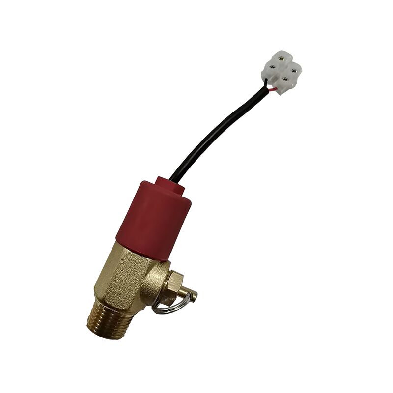
11. Pressure Signal Feedback Device
11.1 Purpose: Installed at the outlet end of the selection valve (for standalone systems without a selection valve, it can be mounted on the manifold). When the mixed gas fire extinguishing agent is released, the pressure switch activates, sending signals to the vent light, audio-visual alarm, and control center.
11.2 Structure: Composed of a valve body, piston, and microswitch, among other components. It features compact size, lightweight design, and high flexibility and reliability.
11.3 Application: Before installation, inspect the piston's operation and measure the microswitch's performance. During installation, ensure the housing is not subjected to any mechanical stress.
|
model
|
design pressure MPa
|
Minimum action pressure (MPa)
|
size for connection
|
|
HXF0.8/17.2
|
17.2
|
0.8
|
R1/2"
|
12. Collection pipe
12.1 Purpose: A mixed gas fire extinguishing agent collected from multiple containers is then transported via the main pipeline to the distribution network within the protected area.
12.2 Structure: The collector pipe is fabricated by welding seamless steel pipes and fittings, with an overall galvanizing treatment. The fitting for the check valve can be manufactured in either single-row or double-row configurations as required.
12.3 Application: The collector tube shall be securely fastened to the cylinder bracket using standard U-bolts.
13. Collection pipe safety valve
13.1 Application: Installed on the collector pipe. Since the combined distribution system employs a selection valve, the collector pipe forms a closed section. When mixed gas accumulates, significant pressure is generated due to temperature effects; therefore, a safety valve is installed at the rear end of the collector pipe.
13.2 Structure: Composed of a valve body and a safety diaphragm. Features a novel design with high safety and reliability.
|
model
|
Nominal diameter
mm
|
design pressure
MPa
|
Pressure relief action pressure (MPa)
|
Import and Export Size
|
|
HXA23
|
6
|
17.2
|
23±5%
|
R1/2"
|
14. Steel cylinder stand
14.1 Purpose: Used to secure the IG-541 fire extinguisher unit.
14.2 Structure: The cylinder stand is constructed from rectangular pipes, featuring exquisite craftsmanship, aesthetic appeal, and robust reliability.
14.3 Application: The cylinder rack is detachable for transportation and can be assembled on-site. The installation site should be level and smooth; if necessary, it may be secured with anchor bolts. The collector pipe should be fixed above the cylinder rack. During assembly, ensure the vertical alignment of the cylinder rack is properly adjusted.
|
specifications
project
|
80
|
90
|
|
Cylinder volume V (L)
|
80
|
90
|
|
Container spacing (mm)
|
350
|
350
|
|
Cylinder stand length L (mm)
|
120+370×(n-1)
|
|
Cylinder stand width B (mm)
|
325 single-bottle pack
|
|
height of the gas cylinder stand H (mm)
|
1900
|
2100
|
15. Nozzle
The nozzle is one of the critical components of the system. Its specifications should be determined based on the specific requirements of the protected area.
15.1 Structure: The nozzle is primarily composed of a nozzle body. The external appearance is shown below:
Working principle: The nozzle is installed within the protected area to spray the atomized fire extinguishing agent, ensuring uniform coverage throughout the area.
16. Low-relief high-seal valve
use :
The low-leakage high-seal valve is installed in the startup pipelines of each zone within the gas system. When a minor leak occurs in the startup device (with pipeline pressure ≤0.1 MPa), the leaking gas is automatically discharged, preventing gas accumulation and pressure buildup that could trigger unintended system malfunctions.
During system operation, as the pressure in the startup pipeline increases rapidly, the low-pass high-resistance valve automatically closes to ensure proper system startup.
16.1 External appearance diagram of the low-discharge high-seal valve:
|
model
|
Nominal diameter (mm)
|
Nominal working pressure (MPa)
|
Air tightness test (MPa)
|
Close Pressure
(MPa)
|
|
HDG0.3/6.6
|
6
|
6.6
|
6.6
|
0.3±0.03
|
16.2 External appearance diagram of the low-discharge high-seal valve:
|
model
|
Nominal diameter (mm)
|
Nominal working pressure (MPa)
|
Air tightness test (MPa)
|
Close Pressure
(MPa)
|
|
HDGO.3/17.2
|
6
|
17.2
|
17.2
|
0.3±0.03
|
17. Pressure relief device
17.1 Purpose: For gas pressure reduction of IG-541.
17.2 Structure: Composed of inlet and outlet flanges, pressure-reducing orifice plates, and sealing rings. Features compact size, excellent sealing performance, and stable, reliable operation.
|
model
|
specifications
|
Design pressure (MPa)
|
Pressure relief plate aperture diameter
|
|
HJYB13.8/40
|
DN40
|
17.2
|
Calculated based on actual figures
|
|
HJYB13.8/32
|
DN32
|
17.2
|
Calculated based on actual figures
|
|
HJYB16.7/50
|
DN50
|
17.2
|
Calculated based on actual figures
|
|
HJYB21.5/65
|
DN65
|
17.2
|
Calculated based on actual figures
|
|
HJYB26.4/80
|
DN80
|
17.2
|
Calculated based on actual figures
|

 Your message must be between 20-3,000 characters!